


📊 Tolerant to a Fault 👩💻
Diving into the Weeds on Tolerance Stacks + MechE Defense Trends

If I was a MechE freshman today, I would hope someone would share The 4-Year Plan with me. Spread the word! 📣
⚠️ Alert
Last newsletter, we got a bunch of questions and a couple requests to jump into the nitty gritty of tolerance stacks.
As this is one of the most used (and least taught) mechanical engineering skills, we figured it warrants a deep dive (we actually made a table and did calculations).
See the complete complete solution to last week’s question below!
🙋♂️ Technical Interview Question
Two components need to fit inside of a bracket (as pictured). Nominally, there is clearance. However, being the wonderfully diligent and talented engineer you are, you know that not all parts are manufactured nominally. Will the parts fit together?
FYI the whole solution is provided below for context, but if you read last week’s newsletter feel free to skip down a few paragraphs.

Main Question
Perform a tolerance stack given the following component drawings to assembly tolerance of the parts at RSS limits.
✅ The Answer
This question is a classic, and tests a skill that you will need to know in any mass production design role. Tolerance stacks are a fundamental skill in a mechanical engineer’s arsenal, and very useful in quantifying clearances, gaps, and general fitments.
First off, what is a tolerance stack, and why do we need it?
For better or for worse, we’re not scientists. We are paid to build things in a cost effective manner. As such, we have to deal with tolerances and manufacturing. When looking to see if the pieces above will fit together, we have a few options, practically speaking.
We can make the teal C shaped piece taller, expanding the MMC of our assembly. This will not only increase the clearance for assembly, but also the material, weight, shipping and manufacturing costs.
Another option would be to crack down on those tolerances; make the components flatter! Hone, lap, grind, and inspect them. Toss out parts not meeting specifications. As you might have guessed, this is also expensive as it impacts yield and throughput.
We can cut down on the part thickness to increase that clearance? This would likely increase manufacturing cost, decrease stiffness and increase likelihood of yielding, but if you want to run the sims on if all that strength is needed, this is an option. When approaching the simulations team to ask for that, just be sure you have looked into other options first and have proper justification for why it’s needed.
Run a tolerance analysis! (Also known as a TA or tolerance stack)
This is a relatively easy way to quantify what that gap will look like in general use cases. One fundamental problem with all of the other strategies, is that you still have no way of knowing how much is enough? You have intuition and guesswork, but…
A) It’s your job to do this. Leave the guessing out if you don’t need it. At every level of every organization, someone is cutting corners. Our job is to figure out exactly how much of that corner to cut!
B) In more complicated assemblies with multiple axes of concern and going through and across more parts, your guess probably won’t be worth much.
So how do we do a tolerance stack?
When I was first asked to do a tolerance stack, the way my manager described it was as an ant crawling along all the parts adding the tolerances through each interface until it reaches the same point again. In many ways, that’s actually pretty much all there is to it (granted it would have helped if he had been more specific, especially for a 3D stack with 6 components and 20+ tolerances but c’est la vie). Let’s dive into the details:
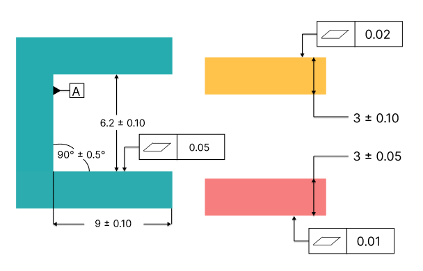
The first thing I like to do is mark the gap/clearance/fit that I am trying to analyze. For us, it’s the following gap:

Based on the drawing, it appears that the part has a nominal clearance of 0.2 mm. Given the tolerance on the teal gap is +/- 0.1, and the red component has a thickness with tolerance +/- 0.05 and the yellow component has a thickness with tolerance +/- 0.10, a quick glance tells us that if each of these components is at the worst case tolerance specification (MMC), the components will not assemble. The gap will be 6.10 while the two parts will have combined thickness 3.05 + 3.10 = 6.15. That, is the reason we check RSS (root sum square - look this up if unfamiliar) tolerances as well! Though not as conservative as the worst case, if we make some generally reasonable assumptions, we can greatly reduce the conservativeness of our estimation for the required gap (resulting in reduced cost).
The most important assumption we are making, and one which we must ensure is in fact true, is that each tolerance we include follows a normal distribution, and in this case, is mean centered. That is to say, that if we look at 100 parts, the majority of them will be centered around the nominal value following a gaussian curve. If there are as many parts at the nominal spec as there are at the bounds, we cannot apply this approach and should instead opt for a Monte Carlo.
A simple RSS tolerance analysis of thickness tolerances alone would give the following:
RSS = ((0.10^2)+(0.05^2)+(0.10^2))^0.5 = 0.15 mm
Given that we have 0.2 mm of nominal clearance, this means that we should actually be fine! An easy way to conceptualize this, is that everything goes wrong in the worst case. But, if we’re looking at RSS tolerances, if something goes wrong in one direction, it’s just as likely something will go wrong in the other direction, cancelling it out! For that reason, RSS tolerances may be smaller than we initially expect. Note that it is still common to add some buffer on top of RSS tolerances if we are able to, given lack of complete knowledge of the validity of the input assumptions (a vendor may say they are hitting a 3 +/- 0.1 mm, but what if the actual distribution is 3.09 +/- 0.01 mm? They technically aren’t out of specification, but your beautiful tolerance stack is now invalid).
There are different levels of fidelity / conservative estimation when it comes to tolerance stacks. The “quick and dirty” tolerance stack for this assembly showed that we have 0.05 mm of clearance. If we’re interested in the detailed analysis (which is likely overly conservative), we need pretend we’re an ant.
Below, each interface is identified.


Many people start with identifying each waypoint on the graphic, though I find it easier to go through the interfaces in my head and write down each tolerance I will need to gather in words, then put together the graphic. To each their own.
Next, we list out each of the interfaces, and go through the associated drawings, collecting tolerances to populate the + & - columns.

Notes:
Tolerances are found from the drawings, but assumptions often have to be made. Typical tolerances of similar parts can be used as an approximation depending manufacturing process, size and vendor.
Here, some additional assumptions we made were:
Yellow top and bottom flatness are the same
Red top and bottom flatness are the same
Teal top and bottom flatness are the same
Teal top and bottom angle
Parallelism of yellow and red components surfaces has negligible impact
Angle tolerance was found by taking: sin(0.5)×9 mm to obtain the vertical impact
Teal gap distance and yellow component thickness were the largest contributors. Most flatness tolerances were negligible.
Flatness tolerances are often overly conservative to include as they are actually unlikely to function symmetrically. This is because it is more likely to have a single peak in your part pushing the interface up than it is for the entire part to happen to be at a valley, allowing the mating geometry to sink in the corresponding amount.
Flatness tolerances (as well as many other GD&T controls) were divided by two before being input into the table. This is because of how GD&T tolerances control surfaces. In the case of flatness, it dictates two parallel planes within which the surface must lie. To make the tolerance diametric, we divide by two.
Worst case clearance is 0.487 mm now! This is significantly higher than the simple worst case clearance check we carried out earlier!
If things are too close for comfort, or if you require even more precision, you may have to then get real world data on thickness and tolerances and use the standard deviation instead of the drawing tolerances.
For high volume applications, use +/- 6 sigmas, this will result in a defect rate of 3.4 PPM (parts per million). For lower volume applications, determine the acceptable failure rate and apply the proper number of standard deviations to your RSS calculations to see if clearance needs to be increased or is acceptable as is.
With an RSS clearance of 0.191, and a nominal clearance of 0.2, it looks like we’re ready to go…? Kind of. Personally, I like to build in a bit more buffer into my tolerance stacks. Plus, it’s an almost certainty that depending on assembly method, they would have a tough time fitting these two plates in with 9 microns of RSS clearance (if this part is supposed to be a running clearance, I definitely wouldn’t give the OK). Firstly, I would consider chamfering the teal entrance to make assembly easier as well as those plate edges if possible. Next, I would evaluate cost impact of increasing clearance by another 0.05 mm depending on constraints and assembly process capabilities.
Ok, class is done for the day, now lets get you a job/internship!
📰 Hardware News
Ansys introduced AI-based simulation tools, Ansys SimAI and Ansys AI+, enhancing workflow efficiency. SimAI utilizes AI for fast, physics-agnostic simulations, allowing engineers to predict design performance quickly. AI+ extends machine learning capabilities to other Ansys tools. In collaboration with Materialise, Ansys will also offer an integrated workflow, merging Ansys Additive Suite with Magics, streamlining the design, simulation, and build process in additive manufacturing. These innovations will be available early 2024 (Try to get them with your educational licenses!).
Shield AI has secured $200 million in a funding round, valuing the company at $2.7 billion, to advance its autonomous flying technology for the military. Shield AI develops autonomous systems like Hivemind, an AI pilot that operates drones without GPS, and V-Bat Teams for drone swarming. Its solutions are sought after due to growing battlefield complexities, including GPS and communication jamming, akin to Tesla's self-driving technology. This reflects increasing investment interest in defense tech amid heightened global military tensions. This is great news for you, a mechanical engineer, given that the high paying exciting EV companies who used to burn cash are slowing hiring (and some are even shutting down).
The Space Force anticipates awarding contracts totaling approximately $20 billion in fiscal 2024 for modernizing military satellite communications (SATCOM) and positioning, navigation, and timing (PNT) systems. This surge, noted by Space Systems Command's Cordell De La Pena, marks a stark increase from $1.6 billion in fiscal 2023. The shift aims to transition from traditional geosynchronous satellites to more resilient architectures, involving smaller, sometimes commercially-owned satellites in lower orbits for enhanced data speed and jamming protection. Key contracts include an $8 billion Evolved Strategic SATCOM program to replace Advanced Extremely High Frequency satellites and a $2 billion initiative to update the ground system for Mobile User Objective System satellites. Additionally, Boeing will receive $464 million to construct the Wideband Global SATCOM satellite with advanced communications and anti-jamming features. This is super exciting for us mechanical engineers because it illustrates a spending trend that will inspire a whole bunch of exciting new satellite startups!
💼 Jobs & Internships
You will feel so much better if you can secure an internship/job before winter break!
Apply Apply Apply!
Freshmen - Check out our 4-Year Plan for how to get internships at startups!
Sophomores - Apply To These Positions
RTX Mechanical Engineering Internship - Summer 2024
Aerojet Rocketdyne Design Engineering Internship
Garmin Design Engineering Internship
Juniors - Full Send Longshots!
Shield AI Mechanical Design Engineering Internship - Summer 2024
Bose Spatial Audio Prototyping Engineer Internship
Skydio Product Design Engineer Internship 2024
Seniors & Graduates - It’s Go (Full) Time!
Super Tough:
General Atomics Aeronautical System Mechanical Engineer
Anduril Mechanical Design Engineer
Tesla Mechanical Design Engineer, Battery Structures, Semi
More Reasonable:
Carrier Engineer, Design Engineering
Westinghouse Electric Co Mechanical Engineer I
Haas Associate Mechanical Engineer
Not seeing what you are looking for? Check out our Job Board for more MechE positions!