


Snap Decisions
Snap-Fit Design 101

⚙️ Mechanical Engineering Resources:
We have put a dozen guides for mechanical engineering students and early professionals on our website
50 Hardware Startups who have raised less than $50 million (perfect internship targets)
How to handle The Behavioral Interview
What it takes to be The 10X Intern
💼 Jobs & Internships
Internship season is in full swing! The race is on!
Freshmen - Check out our 4-Year Plan for how to get internships at startups!
Sophomores - Apply To These Positions
Goodyear Mechanical Engineering Intern
Oshkosh Mechanical Engineering Intern
Vitamix Mechanical Engineering Intern
Juniors - Full Send Longshots!
Astranis Mechanical Engineering Intern
Anduril Manufacturing Engineering Co-op
ASML Mechanical Engineering Design Intern - GEM
Seniors & Graduates - It’s Go (Full) Time!
Super Tough:
Tesla Mechanical Engineer - Sealing
SpaceX Mechanical Engineer - Dragon
COCO Robotics Mechanical Engineer
More Reasonable:
Lawrence Livermore National Laboratory Mechanical Engineer
ADDMAN Additive Engineer
Howmet Aerospace Product Engineer
Haas Packaging Engineer
Not seeing what you are looking for? Check out our Job Board for more MechE positions!
👶 Meme Of The Week
🙋♂️ Interview Practice Question of the Week
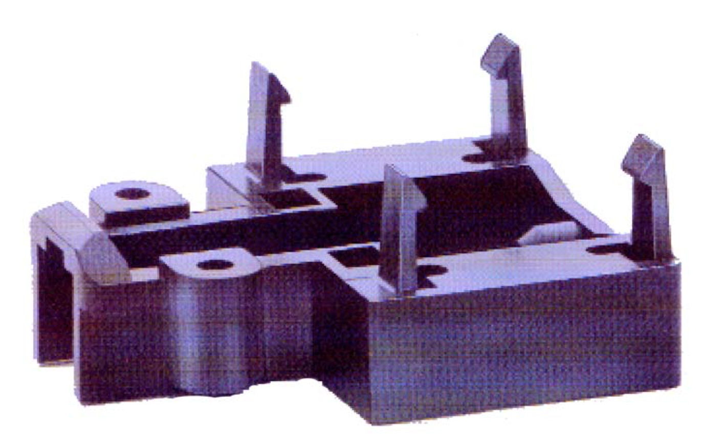
Sally the sagacious bear is working on some snap fits! She wants to make sure that her snap finger won’t significantly yield during the install process. How can she do this?
✅ The Answer
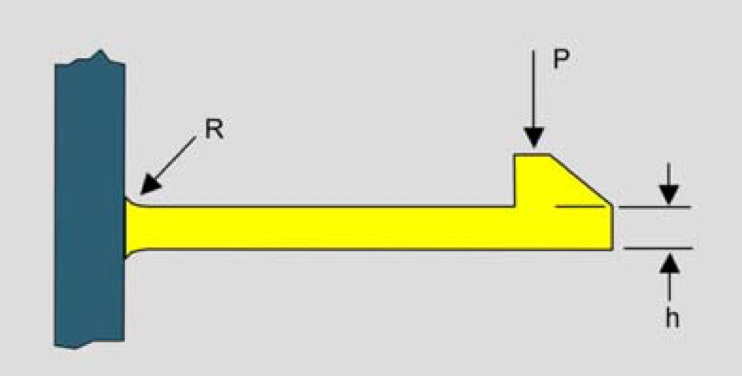
When designing a snap-fit feature (a flexible finger intended to latch onto a mating part) a critical step is to ensure it can bend enough during assembly without permanently deforming, possibly compromising its retaining force or allowing a crack to form.
In order to analyze this, we often treat the finger as a simple cantilever beam. In most cantilever beam scenarios given during interviews, we apply a known force at the free end and determine the resulting deflection and stress. However, snap-fits typically work the other way around: the finger must be pushed a certain distance (a fixed deflection) to engage the snap, and we want to know if that required deflection will push the beam’s stress beyond the material’s yield strength. By approaching the problem from this “deflection load case” perspective, we bypass trial-and-error with the applied force and instead directly relate allowable stress limits to the deflection the finger must undergo. In other words, we start with the permissible stress, then calculate the deflection that corresponds to it, ensuring the snap-fit remains reliable without yielding under its intended deformation.
Step 1: The Standard Beam Equations
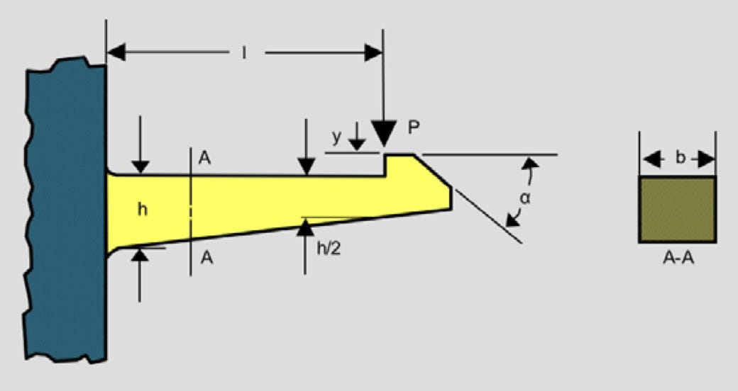
First, recall two key formulas for a cantilever beam with a load F at its free end:
Deflection at the Tip:
Where:
δ = Tip deflection
F = Force at the free end
L = Length of the beam (snap-fit finger)
E = Young’s modulus of the material
I = Second moment of area of the beam’s cross-section
Maximum Bending Stress at the Fixed End:
For an end load F, M = FL, so:
Where:
σ = Maximum bending stress at the beam’s root
c = Distance from the neutral axis to the outermost fiber
Step 2: Eliminating the Load to Relate Stress and Deflection Directly
From:
we get:
Substitute this into the deflection equation:
Cancel and simplify:
Important: If you have it, remember to use flexural strength and flexural modulus of the material given the loading/failure modes.
Step 3: The Final Formula and Its Meaning
You’ve now got a direct relationship between stress and deflection:
This equation lets you jump straight from an allowable stress σ to the deflection δ, considering the beam length L, material stiffness E, and distance from the neutral axis c (sometimes also written as “y” in equations).
Interpretation:
σ: The maximum allowable stress at the beam’s fixed end. If you know the material’s yield stress, keep σ below that to avoid permanent deformation.
δ: The resulting tip deflection at that chosen stress level.
L: The length of your snap-fit finger. Longer fingers deflect more under the same stress.
c: Half the thickness for a rectangular cross-section — thicker beams (larger c) deflect less for the same stress.
E: The material’s stiffness. A higher E means the beam deflects less for a given stress.
This formula is your direct line from “I refuse to exceed this stress” to “This is the deflection I’ll get.” It streamlines the design process by removing intermediate force calculations. It is probably also worth noting here that approximating the snap finger as a cantilever beam is actually quite a simplification. Fiber/fill orientation, fillets, the snap ledge itself, and draft angles may all play a role. If worried and without time to do more detailed simulation (a very simple static structural simulation would likely give a sufficient idea strength), definitely apply a knockdown factor or use more detailed equations from the literature.
Step 4: Applying This to Snap-Fit Design
Material Selection:
Polypropylene (PP): Lower E, very flexible—good if you need more deflection at lower stresses. Personal note: cheap and you get what you pay for. It deflects easily, but also yields easily.
Acetal (POM): Higher E and yield stress—allows a better balance of stiffness and toughness.
Polycarbonate (PC): High stiffness and strength—suitable if you want less deflection for the same stress.
Geometry Adjustments:
Shortening L or increasing thickness (affecting c) reduces δ for the same σ. Tuning L with this formula can provide a good starting point for doing some simulation. Also note that a little bit of localized yielding in simulation isn’t necessarily a deal breaker.
Consider fillets at the base to reduce stress concentrations and keep σ more predictable (can have a massive effect on the stress concentration).
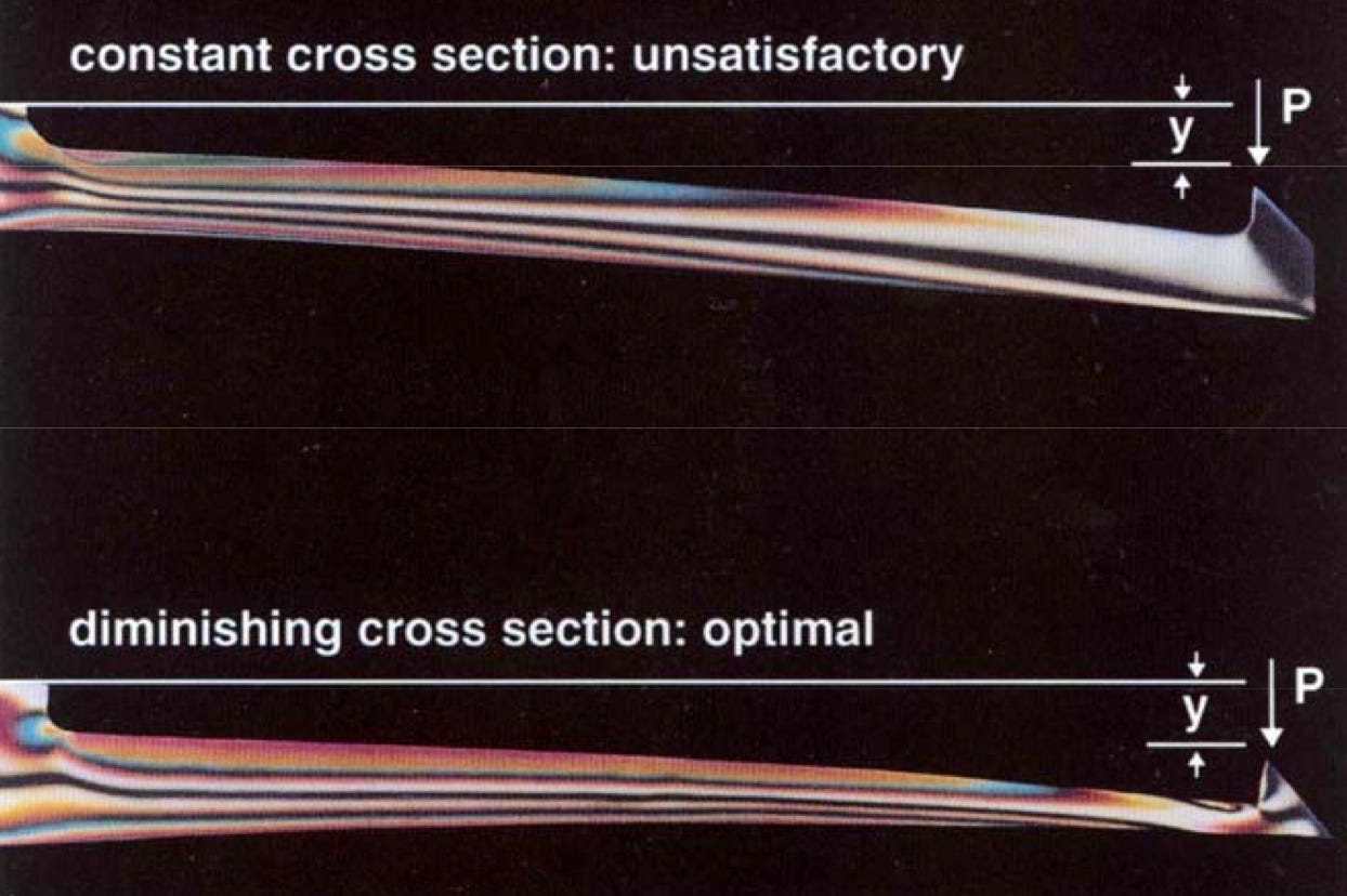
Tapering the thickness can help distribute stress more evenly. It’s a bit unintuitive at first, but this is the accepted way to keep uniform strain across the length of the snap finger. This will help prevent all the strain from happening at the base.
Testing & Validation:
Prototype and test your snap-fit in real conditions. Note that snaps alone are usually not enough, datums are frequently also needed.
Check if the measured deflection matches predictions. Make small tweaks as needed.
Look for evidence of yielding.
An incredible resource for designing snap fits can be found here. It’s the go-to resource I consult when designing snap fits, and I can’t recommend it enough. Even just thumbing through it can be pretty enlightening. There are so many different types of snap joints, and I find the effort to characterize them admirable. A project I always wanted to do was 3D print a few hundred snap finger geometries and characterize insertion force, max deflection, retention force, etc and compile it into a design table for 3D printed snap fits. Anyways, thanks for reading! Hope you learned something.