
GD&T Deep Dive
What, When and Why GD&T??

🦸 Guest Writer: Brad!
This week’s newsletter is a special edition written by written by Brad Hirayama of Pipeline Media Lab in collaboration with Jim Berry. Brad is a biomedical engineer and avid technical communicator. If you like this content, check out some more of his content here!
⚙️ Mechanical Engineering Resources:
We have put a dozen guides for mechanical engineering students and early professionals on our website.
50 Hardware Startups who have raised less than $50 million (perfect internship targets)
How to handle The Behavioral Interview
What it take to be The 10X Intern
👶 Meme Of The Week

The complete guide to DFM and Assembly
Jiga, a platform that connects hardware teams with vetted manufacturers, no black box between you and the people making your parts, put together a guide on the 7 DFM principles that should underpin every design decision. Covers why manufacturability needs to happen early, not as a final check, and how to work with suppliers before your leverage disappears.

You’ve Been Learning GD&T Backwards
Most engineers start with the symbols. The ones who actually use it start with function.
Written in partnership with Jim Berry, Technical Expert and GD&T Instructor
Every mechanical engineer remembers the first time they encountered a fully called-out GD&T drawing. The little boxes stacked with geometric characteristic symbols, tolerance values followed by datum letters, modifiers they’d never seen, and a datum reference frame that seemed to materialize from nowhere. Most engineers do exactly what anyone would do: find a symbol chart, memorize what each icon looks like, and hope that institutional knowledge carries them the rest of the way.
Years later, many are still faking it. They copy tolerance callouts from previous drawings without knowing if the values are appropriate. They assign datums alphabetically rather than functionally. They write drawings that pass design reviews and then generate expensive phone calls from the shop floor.
The problem is not the symbols. The symbols are just notation. The problem is that GD&T is almost universally taught as a symbol language when it is actually a functional specification language - one that starts not with a drawing but with a question: how does this part behave in the assembly? If you skip that question, every callout you write is a guess dressed up as engineering.
This article walks through the framework that makes GD&T systematic rather than intuitive. It will not replace the ASME Y14.5 standard. What it will do is give you a mental model that makes every drawing you read - and every drawing you produce - immediately more deliberate.
Why GD&T Breaks Everyone’s Brain
A professor introduces GD&T by walking through the symbol families: form controls (flatness, straightness, circularity, cylindricity), orientation controls (parallelism, perpendicularity, angularity), location controls (true position, concentricity, symmetry), and profile controls. Students learn what each symbol looks like and what geometric characteristic it governs. Then they move on to the next chapter.
Nobody shows them a real assembly and asks: given how this part functions, which of these controls belong on this drawing, and why? Nobody explains that a flatness callout on a mounting surface exists to prevent the part from rocking against its mating face, or that a position tolerance on a hole pattern exists to guarantee the fasteners can always be installed regardless of where individual holes land within their tolerance zone. The callouts are presented as a catalogue of options rather than answers to specific functional questions.
The result is engineers who can identify a perpendicularity callout but cannot tell you whether it is necessary, whether the tolerance value is correct, or what happens at the shop floor if it is wrong.
There is also a second, more practical source of confusion: the feature control frame itself. That rectangular box that is divided into compartments and appearing next to almost every GD&T callout (shown in figure 1), looks arbitrary until you understand its structure. The frame is read from left to right and contains:
Geometric symbol -> What is being controlled
Tolerance zone shape -> What is the shape of the zone being controlled
Tolerance zone size -> What is the size of the zone
Material Modifier -> Whether your tolerance is fixed or variable
Datum References -> Inspection set up in order of precedence
Engineers who treat the frame as a black box to produce drawings that are technically valid but functionally wrong.
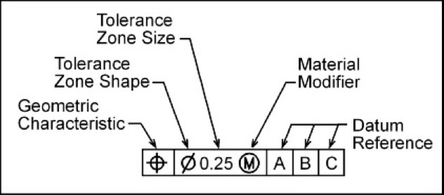
Figure 1. Read from left to right, the anatomy of the feature control frame can be broken down into these 5 pieces.
The third source of confusion is coordinate tolerancing. Most engineers learned to dimension parts with plus-or-minus linear tolerances on X and Y locations. That produces a square tolerance zone. GD&T position tolerance produces a cylindrical tolerance zone. For the same stated tolerance value, the cylindrical zone is approximately 57% larger in area than the square zone. That is the difference between a part passing and failing inspection, and it has nothing to do with whether the part actually fits. Engineers who do not understand this distinction routinely reject good parts or accept bad ones.
The Only 4 Things GD&T Controls
Before the framework, one foundational fact that most engineers are never told explicitly: GD&T controls exactly four geometric characteristics (shown in figure 2). Everything else is notation. Every symbol in the standard is controlling form, size, location, or orientation. That is the complete list. When a drawing looks overwhelming, running each callout through this filter immediately clarifies what the engineer was trying to control and whether the right tool was used to control it.
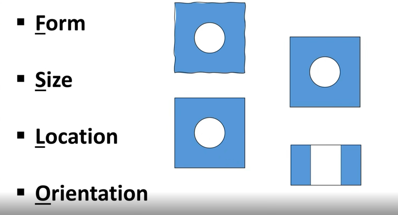
Figure 2. The only four characteristics GD&T controls.
Form
Form describes how straight, flat, round, or cylindrical a surface actually is, independent of any reference to other features. A wall that should be perfectly flat has some bow to it. A hole that should be a perfect cylinder will have some variation in its cross-section as you move along its axis; which means it might be slightly egg-shaped, tri-lobed, or barrel-shaped within its allowable size range. Every manufactured surface has form error. GD&T lets you define how much is acceptable before it affects function.
The four form controls (shown in figure 3) are flatness (surfaces), straightness (line elements or axis), circularity (cross-sections of cylinders or cones), and cylindricity (the full cylinder surface simultaneously). Critically, form controls never reference datums — form is an intrinsic property of a single surface, not a relationship between features. If you see a form control with a datum reference, something is wrong with the drawing.
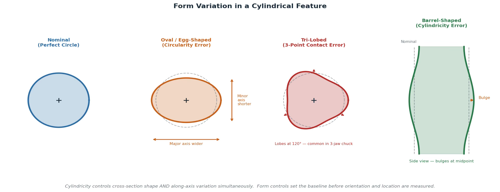
Figure 3. Form variation in a cylindrical feature - Nominal, Oval, Tri-lobed, Barrel
Size
Size defines how large or small a feature can be within its acceptable range. For any feature where two surfaces or elements oppose each other - a hole and a pin that must mate, a tab that must fit in a slot, a block that must slide into a channel - you must specify the allowable size range. The largest pin must always fit in the smallest hole. The smallest pin in the largest hole must not have so much clearance that it rattles or loses alignment.
Size is controlled with coordinate tolerancing: a nominal dimension followed by a plus-or-minus value. A pin called out as 19±0.5 can range from 18.5mm to 19.5mm. A mating hole called out as 20±0.5 can range from 19.5mm to 20.5mm. At their worst-case combination (largest pin (19.5) into smallest hole (19.5)) the pin barely fits. That calculation is not optional. It is the minimum verification required before the drawing leaves your desk.
Location
Location defines where a feature is relative to its functional reference, usually its datum reference frame. A hole can be perfectly round and exactly the right size and still be in the wrong place. Location controls answer the question: how far off from its nominal position can this feature be and still allow the assembly to function?
This is where coordinate tolerancing and GD&T position tolerance diverge most significantly. A plus-or-minus X/Y location tolerance creates a square tolerance zone: the hole axis must fall within a box defined by the bilateral tolerances in each direction. A GD&T position callout with a diameter symbol creates a cylindrical tolerance zone centered on the true position of the hole. For a stated tolerance of ±0.5mm in coordinate tolerancing, the square zone has an area of 1.0×1.0mm = 1.0mm². The equivalent cylindrical zone with a diameter of 1.0mm has an area of π(0.5)² ≈ 0.785mm² - roughly 57% more usable tolerance area - while still guaranteeing the same assembly performance as the square zone. More tolerance, no functional compromise.
Orientation
Orientation controls how tilted a feature is relative to a datum reference. A hole axis that should be perpendicular to a mounting face but has angular deviation. A surface that should be parallel to another but has a slight tilt. Orientation always references at least one datum because tilt is only meaningful relative to something else.
The three orientation controls are perpendicularity (90° nominal), parallelism (0° nominal), and angularity (any other angle). Each defines a tolerance zone - two parallel planes, or a cylinder - within which the surface or axis must fall when the part is oriented relative to the specified datum. Every datum reference in a feature control frame is, at minimum, an orientation control. Location controls are always orientation controls as well, because you cannot specify where something is without implicitly constraining how it is tilted.

Five engineers made one decision each that defined their careers. Margaret Hamilton, Gordon Moore, Andy Grove. The frameworks they used are in a free PDF - yours when you subscribe to Pipeline Media Lab at this link or by scanning the QR code.
The Function-First Framework
With the four characteristics as a foundation, here is the framework that makes GD&T systematic. Three steps, applied in sequence every time, to every part.
1. Understand the assembly before you touch a drawing
The first thing you do when approaching a part is not open the drawing. It is to understand how the part interacts with its mating features. Where does it sit? What surface does it press against first? What locates it in-plane? What prevents it from rotating? What has to fit inside it or around it? Take the square block example shown below.
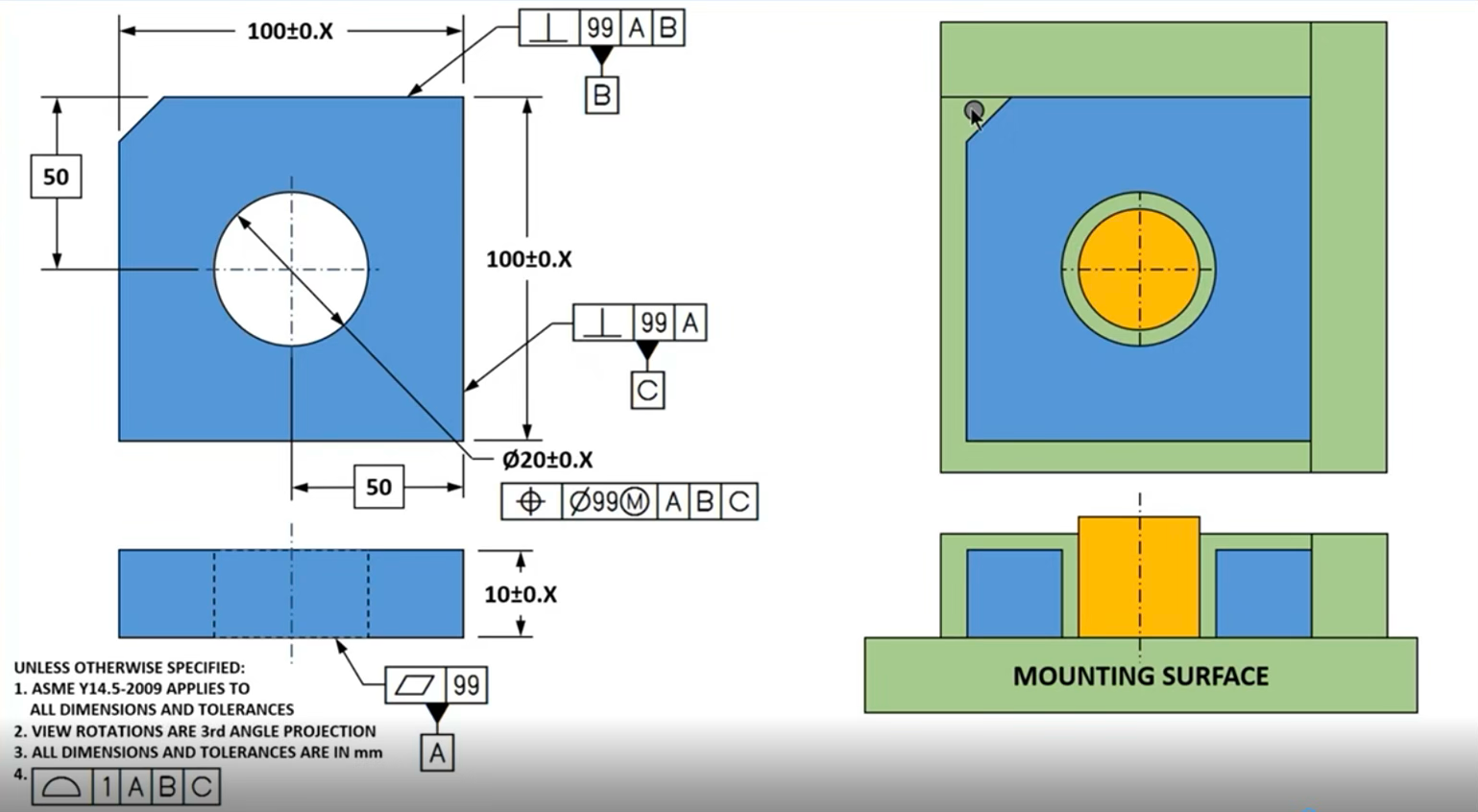
Figure 4. The square block example from Jim’s Webinar.
This is a square machined block - a fixed thickness, a centered hole at ⌀20mm, and a chamfer on one corner that acts as a poka-yoke, forcing the part to install only one way. Before a single tolerance is written, the only question that matters: how does this part sit in the assembly?
The block seats down on a flat mounting surface first - that’s datum A, the primary reference. It then slides laterally until it contacts a side surface - datum B, the secondary. Finally it slides in the perpendicular direction until it contacts a third surface - datum C. Three surfaces. Three points of contact. Three datums.
Notice what this does to the feature control frames. Datum A gets a flatness qualifier; which means if the bottom surface rocks, the entire reference frame is unreliable. Datum B gets a perpendicularity qualifier back to A - the side surface must be controlled relative to the primary before it can be used to locate anything else. Datum C gets the same treatment. Each datum qualifies the next one. The callouts build on each other in the same sequence the part physically seats.
The hole is the last thing specified. Its size tolerance (⌀20 ± X, left as a placeholder until a tolerance stack is calculated) controls form and size. Its position callout references A, B, and C in that order, controlling orientation - the axis must be perpendicular to A and parallel to B and C - and location, 50mm out from datum planes B and C. The chamfer goes to the default profile tolerance; no specific callout needed because the poka-yoke geometry prevents mis-installation regardless.
2. Classify every feature as a surface or a regular feature of size
Once you understand the assembly, look at every feature on the part and ask a single question: can I grab this with a caliper and get a repeatable measurement between two opposing points or surfaces? If yes, it is a regular feature of size. If no, it is a surface.
Cylindrical features of size are the most common: holes and pins. The inner diameter of a hole and the outer diameter of a pin are both features of size: you can grab either with calipers and get a direct size reading. Planar features of size are equally important but less frequently recognized: a block that must fit into a slot, or a tab that must fit into a notch. If you can grip both sides of the opening or both sides of the tab simultaneously, it qualifies as a regular feature of size (shown in figure 5).
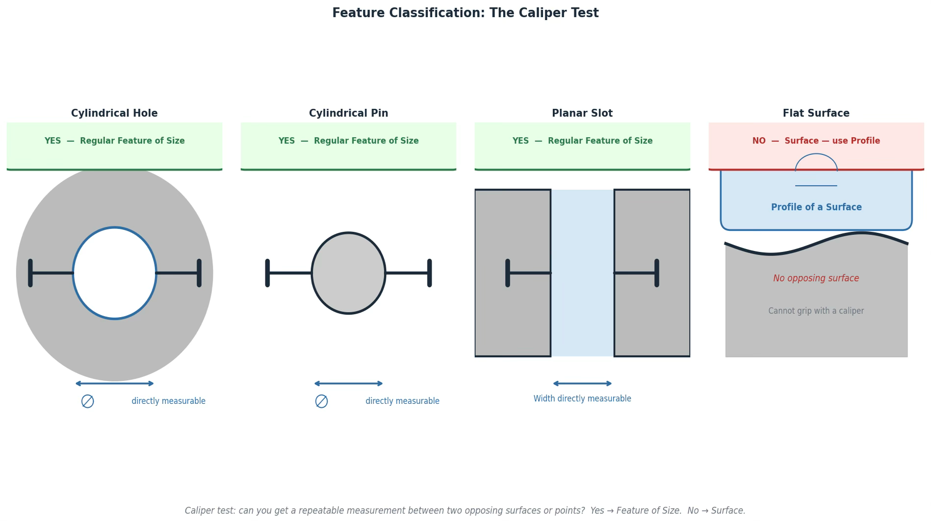
Figure 5. The caliper test, an easy way to identify regular features of size.
Most engineers blur this distinction and end up with drawings where surfaces get size tolerances applied incorrectly, or features of size are controlled with profile callouts that don’t communicate what was intended. The result is a drawing your manufacturer has to interpret rather than read.
3. Assign datums in functional order - A, B, C maps directly to how the part seats
Datums are not arbitrary labels. Datum A is the most important mating interface for your part in the assembly. Datum B is the second. Datum C is the third. The sequence describes the physical order in which the part contacts its mating features.
For a bracket that mounts to a wall: datum A is the flat back surface (the part seats against the wall here first), datum B is established by the pattern of two fastener holes (these locate the bracket in-plane once it’s against the wall), and datum C is the third constraint. The inspection setup follows exactly: set the part against A, then locate against B, then check everything else relative to that reference frame.
A flat primary datum surface (datum A) constrains three degrees of freedom: translation perpendicular to the surface, and rotation about two axes parallel to it. A secondary datum feature - often a hole pattern or a cylindrical surface - constrains two more: translation in the two remaining in-plane directions. A tertiary datum constrains the final degree of freedom: rotation about the axis perpendicular to the primary surface. Six degrees of freedom total. Three datums, in functional order, lock the part completely.
The datum reference in any feature control frame tells the inspector exactly how to set up the part for measurement. The sequence is the assembly process, translated into inspection language. Once you see it this way, datum A–B–C stops being alphabet soup and starts being a precise description of how your part lives in the world.
One nuance that trips up even experienced engineers: many datum features need a form qualifier before they can serve as a reliable reference. A flat surface called out as datum A should also carry a flatness callout - qualifying that surface to be flat within some tolerance before it establishes the primary datum plane. A surface that rocks by 0.3mm cannot reliably establish a plane. The qualifier ensures the datum feature is good enough to be a datum.
The Interview Question
Companies that are bringing on mechanical engineers, especially in consumer electronics, robtics, aerospace, to name a few, test GD&T in almost every technical interview. The question will usually look something like this (shown in figure 6) and you’ll be asked:
Here’s a wall bracket. It mounts to a surface, holds a divider panel in a central opening, and is secured by two fasteners through clearance holes. Walk me through how you would fully define it with GD&T.
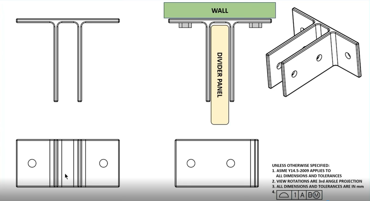
Figure 6. A Mock interview question based on a bracket mounted to a wall.
The easy answer is to just call out symbols based on what you see. “I’d put a flatness callout on the mounting surface, true position on the holes, and a size tolerance on the opening.”
Symbols listed. No rationale. No tolerance values. No explanation of why the datums are in the order they’re in, or how you’d know if any of those numbers were right. Any engineer who has skimmed a GD&T textbook can produce this answer. It tells the interviewer nothing about whether you could actually spec a real part.
Here’s how you should answer this problem:
Before I write anything, I want to understand the assembly sequence. This bracket seats its flat back surface against the wall - that’s the first and most critical interface, so that surface is datum A. I’d add a flatness qualifier of 0.1mm to it. If the surface is more than 0.1mm out of flat, the bracket will tilt or rock against the wall, and the divider panel inside the opening won’t sit perpendicular. The flatness qualifier is protecting the function of everything else downstream.
The two fastener holes are next. Once the bracket is seated against the wall and the fasteners are torqued, those holes locate the bracket in-plane: they constrain it from translating or rotating in the plane of the wall. Both holes together establish datum B as a pattern, not individually. I’d add a position callout to control their perpendicularity to datum A and the spacing between them, with the tolerance value left as X until I’ve done a proper tolerance stack. You don’t put numbers in until you know what the assembly can actually absorb.
The divider panel opening is a regular feature of size - I can grip both walls of it with calipers, so it gets a size tolerance, not a profile callout. If the panel is 24.5 ±0.2mm wide, the opening needs to be 25 ±0.2mm. Worst case, the largest panel is 24.7mm and the smallest opening is 24.8mm: a 0.1mm clearance, the panel installs. That calculation has to be done before the drawing ships, not after first articles come back wrong.
The center plane of that opening also gets a position callout tied back to A and B. This controls where the opening actually sits relative to the fastener holes — it ensures the panel lands where it’s supposed to in the assembly, not just that it’s the right width. Finally, the two smaller holes that secure the panel get their own size tolerances and position callouts, also referenced to A and B. Everything traces back to the same datum reference frame.
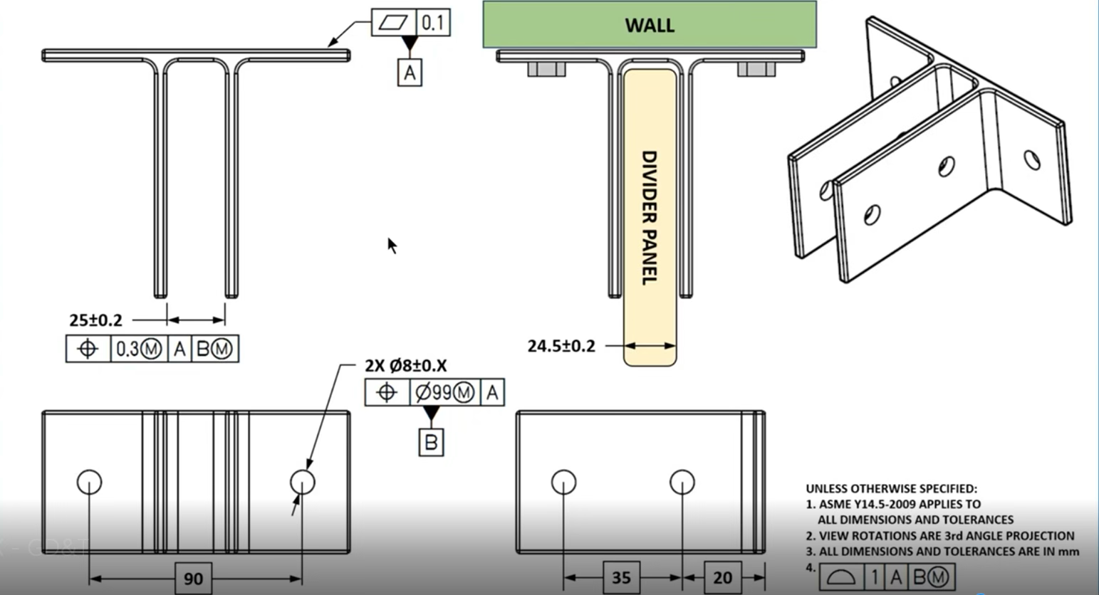
Figure 7. Fully dimensioned with datums and GD&T tolerancing.
That answer demonstrates five things simultaneously: assembly awareness (datums assigned in functional order, not alphabetically), feature classification (the opening identified as a regular feature of size before any callout is chosen), worst-case analysis executed on the spot with real numbers, a complete datum reference frame that mirrors the inspection setup exactly, and the discipline to leave tolerance values open until the math supports them. Any one of those signals competence. All five together signals someone who has actually built hardware.
The Bonus Question: Unlocking MMC
You applied a position callout to the fastener hole pattern. What happens to that tolerance zone when you added an M modifier?
To answer this question, you have to go back to the bracket. The two clearance holes establish datum B: they locate the bracket against the wall once the fasteners are torqued. The position callout controls their perpendicularity to datum A and the spacing between them. Now you add the M modifier to that callout and you’re calling out the maximum material condition.
Maximum Material Condition means the stated tolerance applies when the hole is at its smallest allowable size or the most material remaining, the tightest condition. For a clearance hole, that is its narrowest diameter. As the hole grows larger - departing MMC toward Least Material Condition - it earns bonus tolerance equal to that departure. The position zone expands.
Here’s the math: Say the clearance holes are called out at ⌀14 ±0.2mm. MMC is ⌀13.8mm. The stated position tolerance at MMC is ⌀0.5mm. A hole produced at ⌀14.0mm has departed MMC by 0.2mm - it gains 0.2mm of bonus tolerance, bringing its total position zone to ⌀0.7mm. A hole produced at LMC of ⌀14.2mm gains 0.4mm of bonus, for a total zone of ⌀0.9mm. The fastener still fits - a larger clearance hole gives the bolt more room to find its way in. More hole, more forgiveness, same functional result.
This is why the M modifier exists. Without it, every hole is held to the same ⌀0.5mm position zone regardless of produced size. With it, larger holes - which are easier to assemble and naturally more forgiving - get a larger zone. The parts that should pass, pass. The ones that shouldn’t, don’t. Manufacturing yield goes up without touching the functional requirement.
Now connect it back to the divider panel opening. The slot was called out at 25 ±0.2mm against a panel of 24.5 ±0.2mm. The position callout on the slot’s center plane was referenced back to A and B. You could apply an M modifier there too: a wider slot opening has more room to accommodate the panel even if its center plane is slightly off. The functional requirement is that the panel goes in. A 25.4mm opening that’s 0.3mm off-center still accepts a 24.7mm panel cleanly. A fixed position zone wouldn’t know that. MMC does.
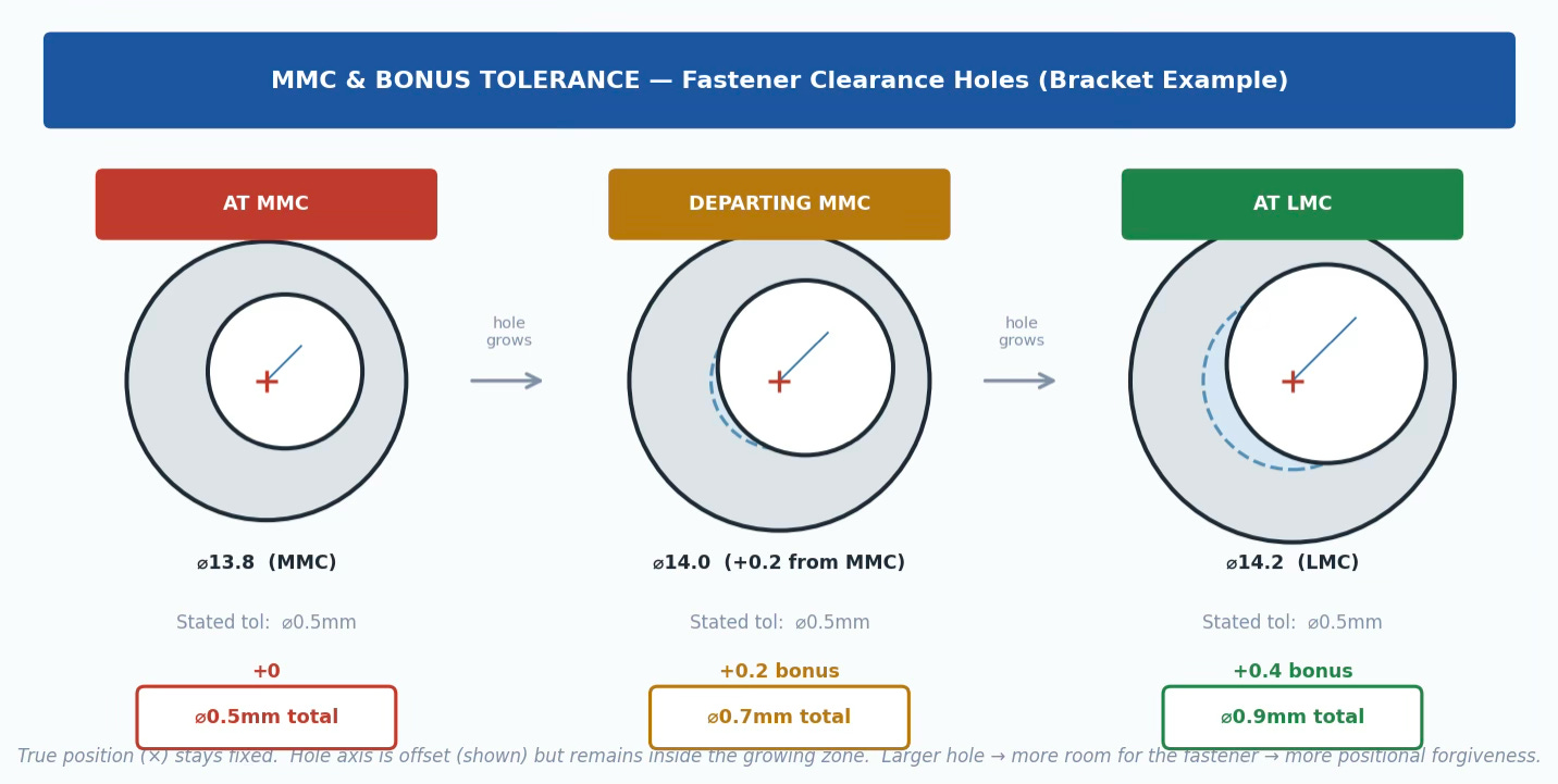
Figure 8. MMC Bonus Tolerance: Position zone grows as hole grows.
GD&T is not a documentation formality. It is a precision communication protocol between the engineer who specifies a part and every person who has to make it, inspect it, and assemble it. A drawing that uses GD&T correctly eliminates ambiguity at every step in that chain. A drawing that uses it incorrectly or uses it as decoration on top of coordinate tolerancing, creates ambiguity that compounds downstream, from first articles to production ramp.
The engineers who build hardware that works the first time are the ones who asked the right question first: how does this part behave in the world? Start there. The symbols will follow.